

Install a PTV 1000 sampling point
Plan how water gets to the flow body, how it drains and how the instrument will be checked during routine operation.
Plan your sampling pointStart with the sample route
Trace the take-off, available pressure and expected flow through a normal operating cycle. Check what happens when a pump changes state or a filter returns to service. Allow enough room to isolate the sample, inspect the drain and remove the sensor head for servicing.
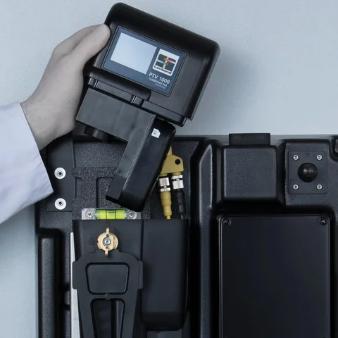
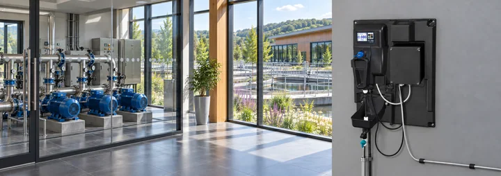
From the take-off to the drain
Trace the full sample route before finalising the panel position or pipework.
Plan the sample routePrepare for commissioning
Agree the checks you will run before handing the measurement over to operations. Capture the optical method, baseline reading, verification result and what the control room should see if sample flow or communications are lost.

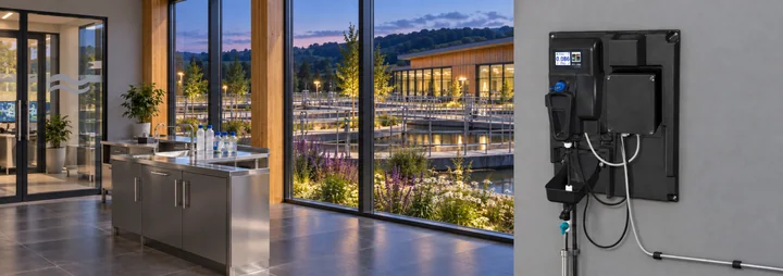
Install with the manufacturer’s instructions to hand
Check the operating instructions and wiring reference for your exact equipment.
View technical documentsWatch the assembly before going to site
See how the mounting cleat, flow body and fluidics manager fit together. Compare the video with the operating instructions for your instrument before planning access and pipework.

Configure your PTV 1000
Choose where you’ll measure, which optical method applies and how the reading will reach your plant system. Save a brief for discussion with PMA.
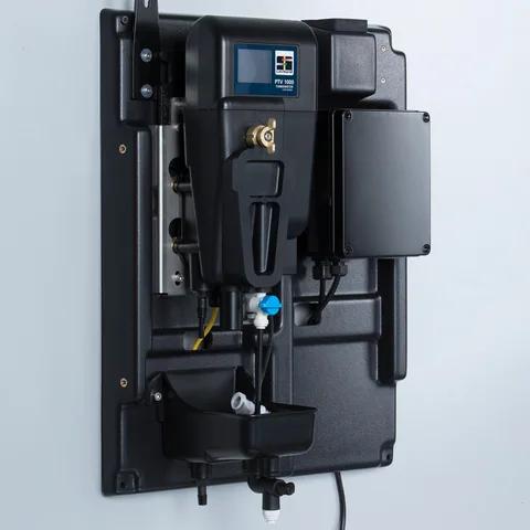
Your configuration brief
- Monitoring point
- Filter outlet
- Optical model
- Confirm the optical method
- Plant connection
- Confirm plant connection
Confirm the sample conditions and exact junction box with PMA before specifying an instrument.
Planning a PTV 1000 installation?
Gather the sample, method and plant connection details for a discussion with PMA.
Prepare your enquiryStart with the sample
Have the sampling point, expected turbidity and operating flow to hand.